 |
|||
|
|
|||
|
Page Title:
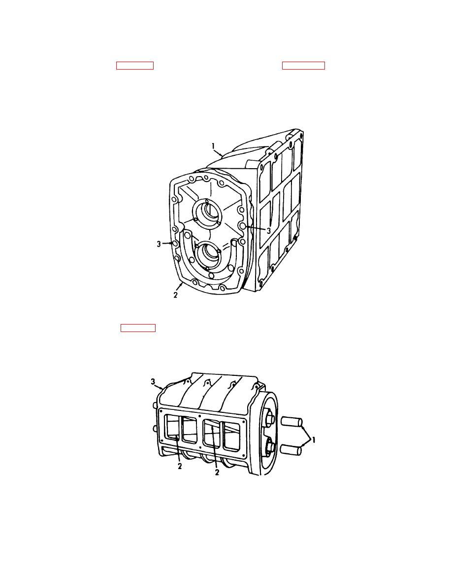
Figure 3-35. Front End Plate, Installation. |
|
||
| ||||||||||
|
|
 TM 55-1930-208-24
(5) Refer to figure 3-35 and apply sealing compound (item 22, Appendix C) to front of housing (1).
(6) Install blower front end plate (2) using a soft mallet to drive the plate over the dowel pins.
(7) Install two screws (3) to secure end plate (2) to housing (3). Torque screws to 5-10 lb-ft (7-14
Nm).
Figure 3-35. Front End Plate, Installation.
(8) Refer to figure 3-36 and place an oil seal pilot (1) on the short (non-splined) end of each rotor
shaft (2).
(9) Place the rotors (2) in mesh with the missing serrations of the splines alined. Insert the rotors (2)
into the housing (3) with the right hand helix rotor at the top.
Figure 3-36. Rotor, Installation.
3-65
|
|
Privacy Statement - Press Release - Copyright Information. - Contact Us |
