 |
|||
|
|
|||
|
Page Title:
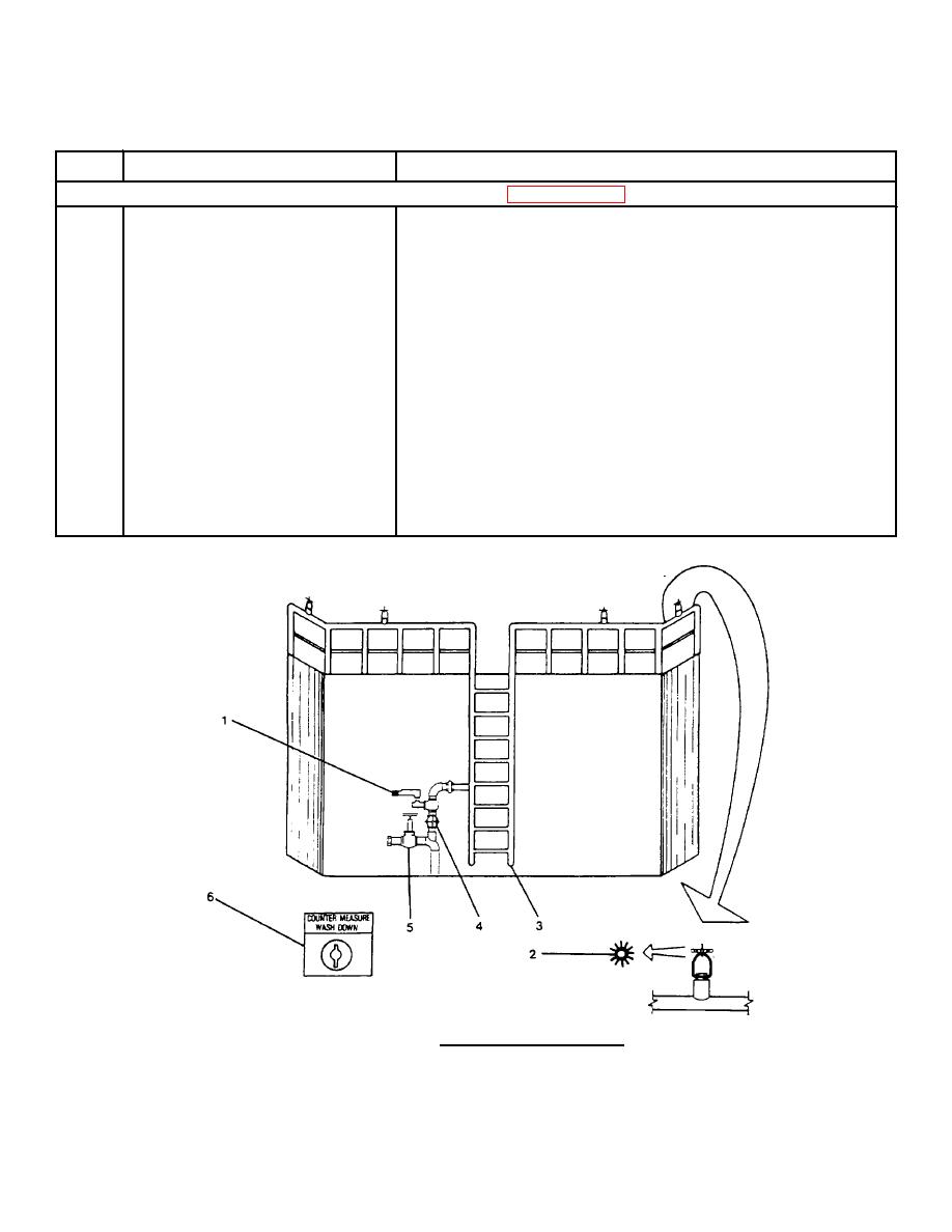
FIGURE 2-100. Countermeasure System. |
|
||
| ||||||||||
|
|
 TM 55-1915-200-10
Table 2-1. Description of Operator's Controls and Indicators - CONT
Key
Control or Indicator
Function
Countermeasure System (FIGURE 2-100)
1
Solenoid Valve
Opens to provide firemain water to system.
2
Sprinkler Head
Deflects water in a circular pattern.
3
Drain Valve
Drains water from countermeasure piping
system.
4
Manual Valve
Hand operated valve to piping system.
5
Manual Valve
Valve to fire station No. 12.
6
ON/OFF
Switch; electrical key operated switch
that controls solenoid valve.
(Located in
pilothouse on the PORT half bulkhead below
the trim clinometer.)
FIGURE 2-100. Countermeasure System.
2-226
|
|
Privacy Statement - Press Release - Copyright Information. - Contact Us |
