 |
|||
|
|
|||
|
Page Title:
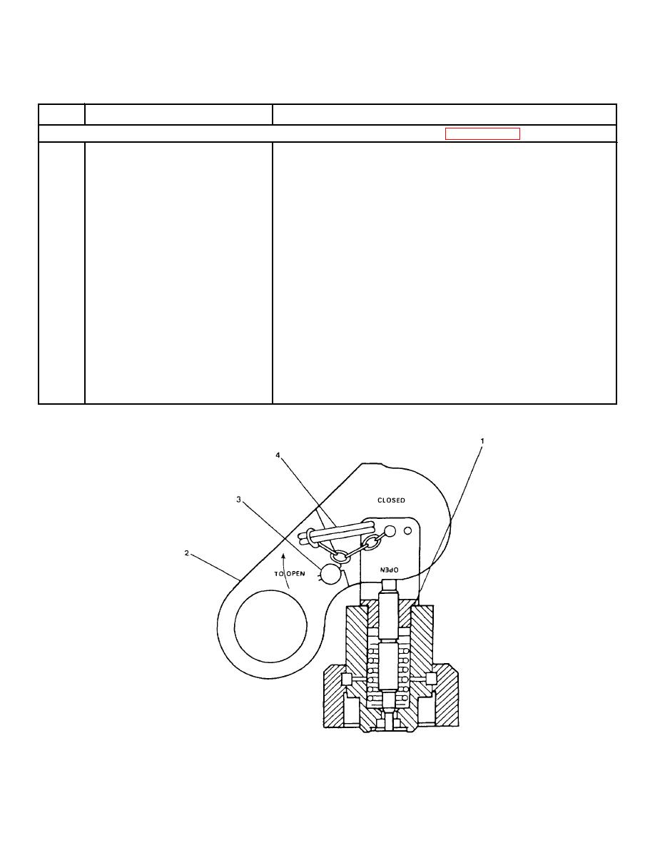
FIGURE 2-46. Lever Operated Control Halon 1301 Fire Suppression System. |
|
||
| ||||||||||
|
|
 TM 55-1915-200-10
Table 2-1. Description of Operator's Controls and Indicators - CONT
Key
Control or Indicator
Function
Lever Operated Control Halon 1301 Fire Suppression System (FIGURE 2-46)
1
Lever Operated Control
A lever operated control is mounted on
a carbon dioxide (CO2) cylinder at the
forward and aft bulkheads in the upper
machinery room for engine room and
discharge.
2
Lever
Pull up to release CO2 charge which
activates Halon release.
3
Seal Wire
Verifies that system has not been
activated. If seal wire is missing or
broken, system has been used.
4
Locking Pin
Pull completely out before lever is
pulled to release CO2. Prevents
accidental tripping of CO2 release for
Halon system.
FIGURE 2-46. Lever Operated Control Halon 1301 Fire Suppression System.
2-147
|
|
Privacy Statement - Press Release - Copyright Information. - Contact Us |
