 |
|||
|
|
|||
|
Page Title:
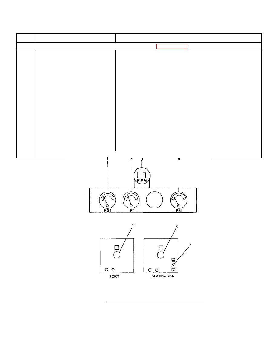
FIGURE 2-22. Generator Set Engine 250 KW Control Panel. |
|
||
| ||||||||||
|
|
 TM 55-1915-200-10
Table 2-1. Description of Operator's Controls and Indicators - CONT
Key
Control or Indicator
Function
Generator Set Engine 250 KW (FIGURE 2-22)
1
P.S.I.
Indicates lubricating oil pressure.
2
F
Indicates lubricating oil temperature.
3
R.P.M.
Indicates engine RPM.
4
P.S.I.
Indicates fuel oil pressure.
5
Emergency Stop Switch
Causes emergency stop of port generator
engine.
6
Emergency Stop Switch
Causes emergency stop of starboard
generator engine.
7
ON-OFF Switch
Controls starting air pressure to
starboard generator engine.
FIGURE 2-22. Generator Set Engine 250 KW Control Panel.
2-102
|
|
Privacy Statement - Press Release - Copyright Information. - Contact Us |
