 |
|||
|
|
|||
|
Page Title:
FIGURE 4-94. Measure Installed Cam Bushings. |
|
||
| ||||||||||
|
|
 TM 55-1905-223-24-4
j.
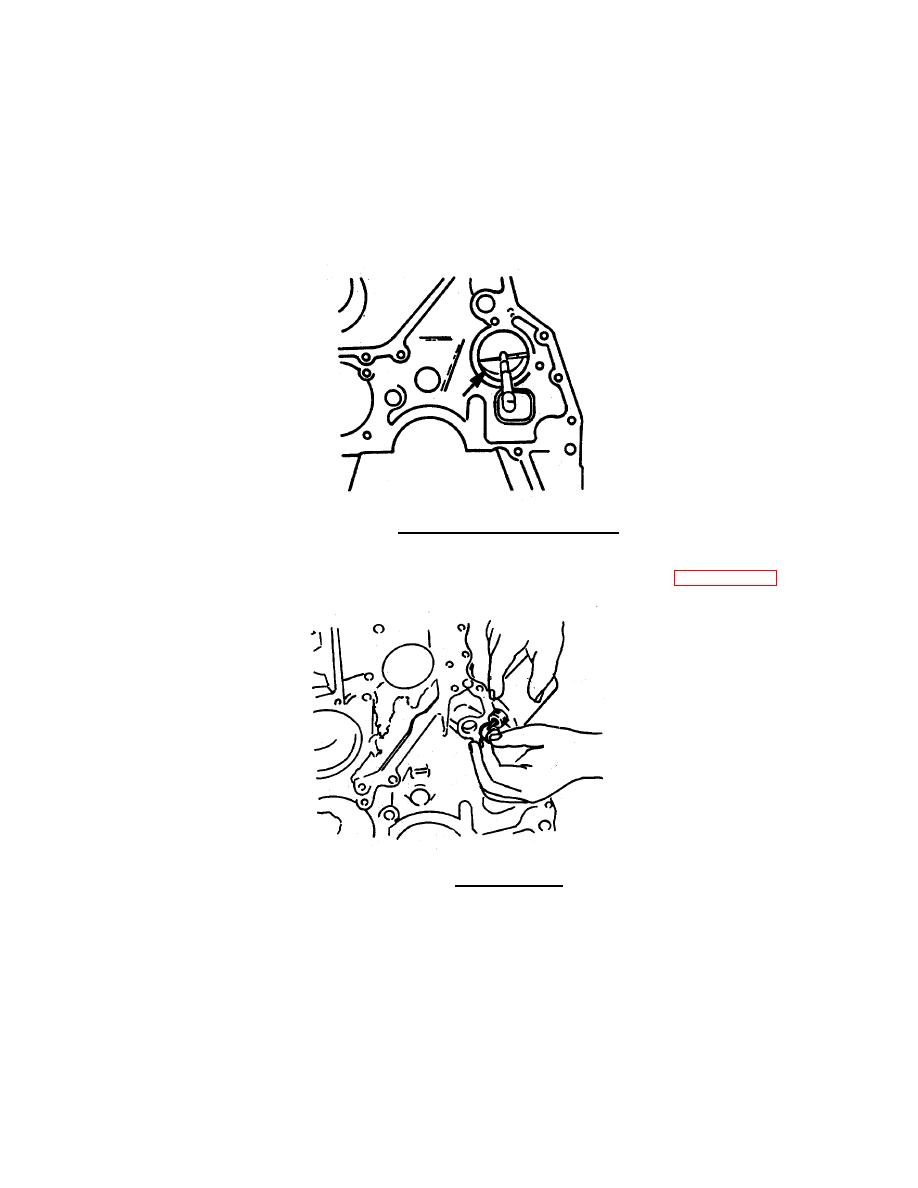
Use an inside dial bore gauge to measure the installed cam bushing. (FIGURE 4-94)
DIAMETER
mm
inch
54.089
min 2.1295
54.139
max 2.1314
FICURE 4-94. Measure Installed Cam Bushings.
k.
Apply a bead of loctite 277 around the outside diameter of the oil passage cup plugs. (FIGURE 4-95)
FIGURE 4-95. Applying Loctite.
4-65
|
|
Privacy Statement - Press Release - Copyright Information. - Contact Us |
