 |
|||
|
|
|||
|
Page Title:
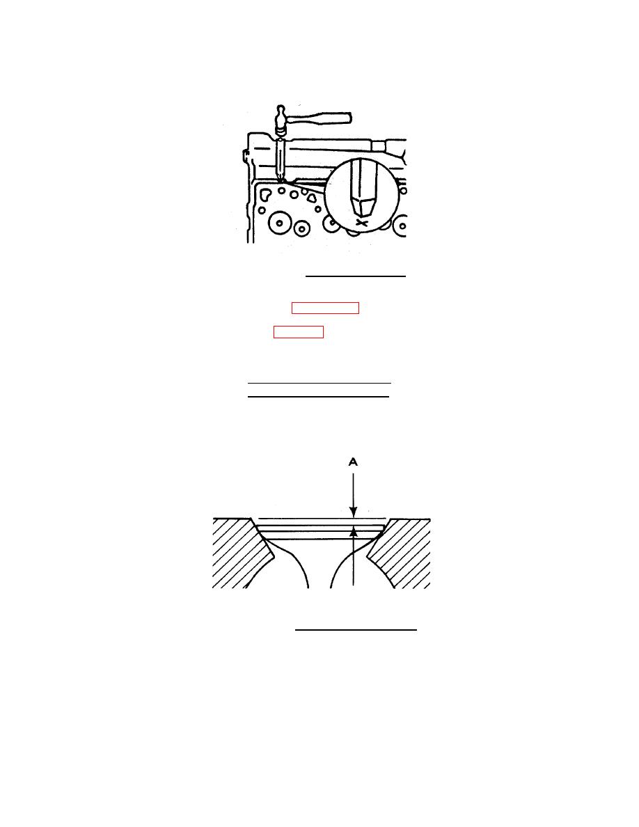
FIGURE 4-15. Grinding Valve Seats. |
|
||
| ||||||||||
|
|
 TM 55-1905-223-24-4
e.
Grinding Seats. Previously re-ground seats can be replaced with service seats. The marked illustration
indicates a previously ground valve seat.
FIGURE 4-15. Grinding Valve Seats.
(1) Install the valves in their designated location and measure valve depth. The depth is the distance from
the valve face to the head deck as shown in FIGURE 4-16.
(2) Record the depth of each valve as (A). Table 4-3 gives minimum (MIN) and maximum (MAX) depth.
Table 4-3. Valve Depth
in
mm
0.039
MIN
(0.99)
0.060
MAX
(1.52)
FIGURE 4-16. Checking Valve Depth (A).
4-17
|
|
Privacy Statement - Press Release - Copyright Information. - Contact Us |
