 |
|||
|
|
|||
|
Page Title:
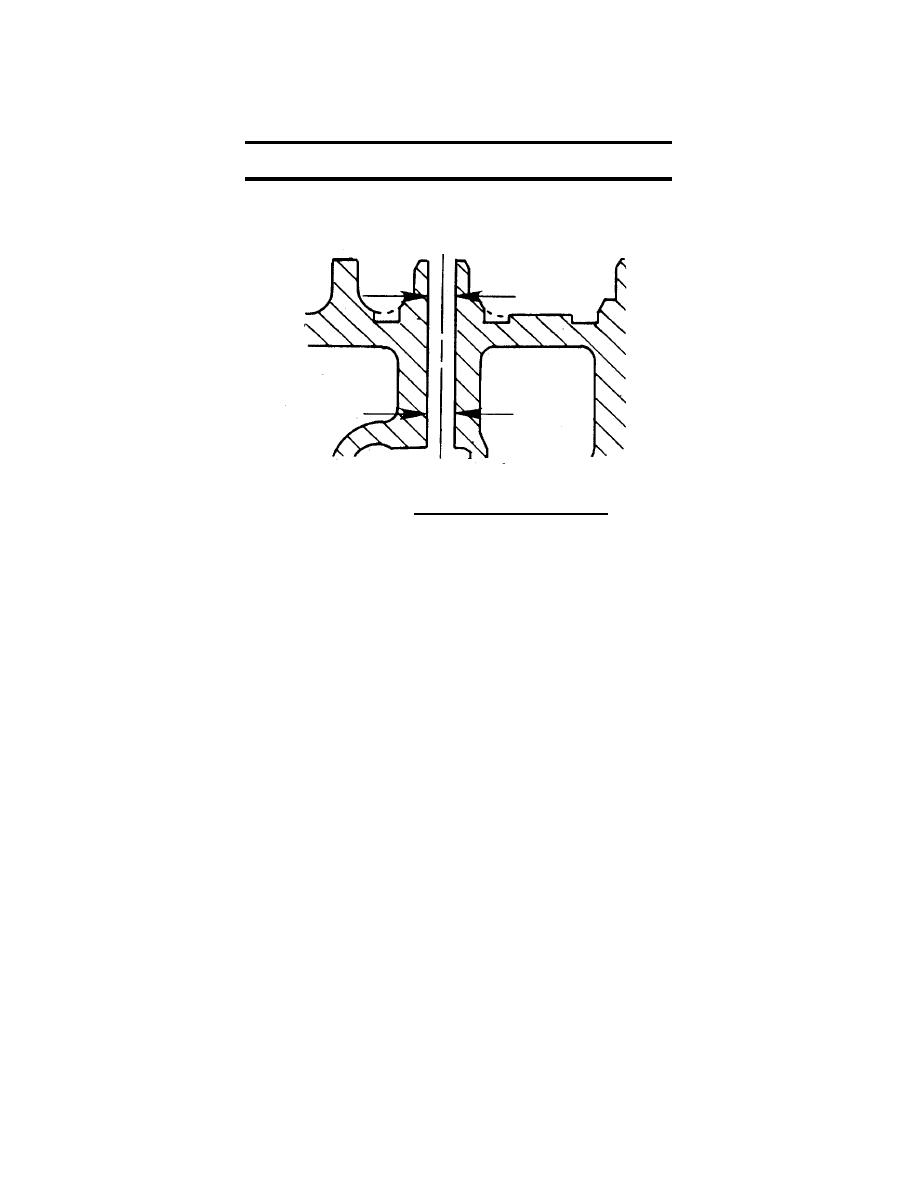
FIGURE 4-10 . Measuring Valve Guide Bore. |
|
||
| ||||||||||
|
|
 TM 55-1905-223-24-4
Table 4-1.
Diameter
in
mm
0.3157
MIN
(8.019)
0.3185
MAX
(8.089)
FIGURE 4-10 . Measuring Valve Guide Bore.
g.
Inspect the head surface for nicks, erosion, etc. Check the head for distortion.
Limit
Variation:
0.0039 inch (0.010 mm) within a 2.0 inch (50.8 mm) diameter area.
0.003 inch (0.075 mm) overall end to end or side to side.
h.
Clean and Inspect the Valves.
(1)
Clean the valve heads with a soft wire wheel.
(2)
Polish the valve stem with crocus cloth.
4-13
|
|
Privacy Statement - Press Release - Copyright Information. - Contact Us |
