 |
|||
|
|
|||
|
Page Title:
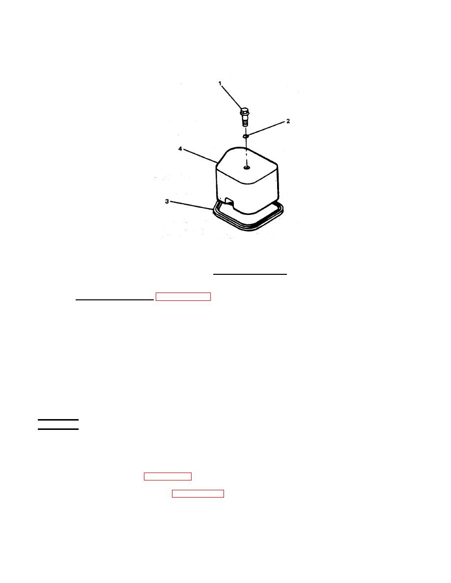
FIGURE 3-37. Valve Cover Removal . |
|
||
| ||||||||||
|
|
 TM 55-1905-223-24-4
FIGURE 3-37. Valve Cover Removal .
b.
Remove Rocker Levers. (FIGURE 3-38)
(1)
Loosen lock nuts (4) on rocker lever adjusting screws (8) and oosen
l
screws until they stop.
(2)
Remove capscrews (1) from the support (11).
(3)
Remove support/head bolts (2) from the shaft support.
(4)
Remove expansion plugs (5), retaining rings (6), and flat washer (7).
(5)
Remove rocker lever (10, 3) nuts (4), and machine screws (8) from push
rods (9).
REPAIR
Repair at this level of maintenance is by replacement of: Lock nuts (4),
adjusting screws (8), and rocker lever (10).
a.
Inspect for cracks and wear in the bore and the surface whichmakes contact
with the valve stem (FIGURE 3-39).
b.
Measure the bore with gauge (FIGURE 3-40).
3-52
|
|
Privacy Statement - Press Release - Copyright Information. - Contact Us |
