 |
|||
|
|
|||
|
Page Title:
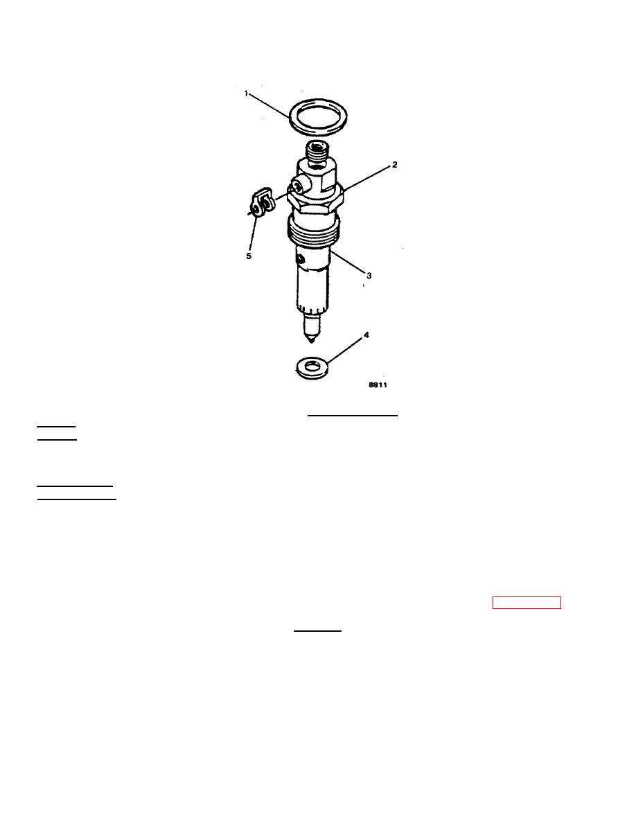
FIGURE 2-38. Fuel Injector Group. |
|
||
| ||||||||||
|
|
 TM 55-1905-223-24-4
FIGURE 2-38. Fuel Injector Group.
REPAIR
Repair at this level of maintenance is by replacement of: gasket (1), injector
assembly (3), sealing washer (4) and banjo connector seal (5).
REPLACEMENT
a. Replace new gasket (1).
b. Apply a coat of anti-seize compound to the threads of the injector holddown nut and between the top of the nut
and injector body.
c.
Replace injector (3) and sealing washer (4).
d. The protrusion on the side of the nozzle fits into a notch in the head to orient the injector. (FIGURE 2-39).
CAUTION
Some sockets can damage the fuel drain outlet sealing surface.
e. Use a 24mm deep well socket to tighten the hold-down nut to 44 ft-lb (60 N ) torque.
m
f.
Install fuel drain manifold banjo connector seal (5).
2-100
|
|
Privacy Statement - Press Release - Copyright Information. - Contact Us |
