 |
|||
|
|
|||
|
Page Title:
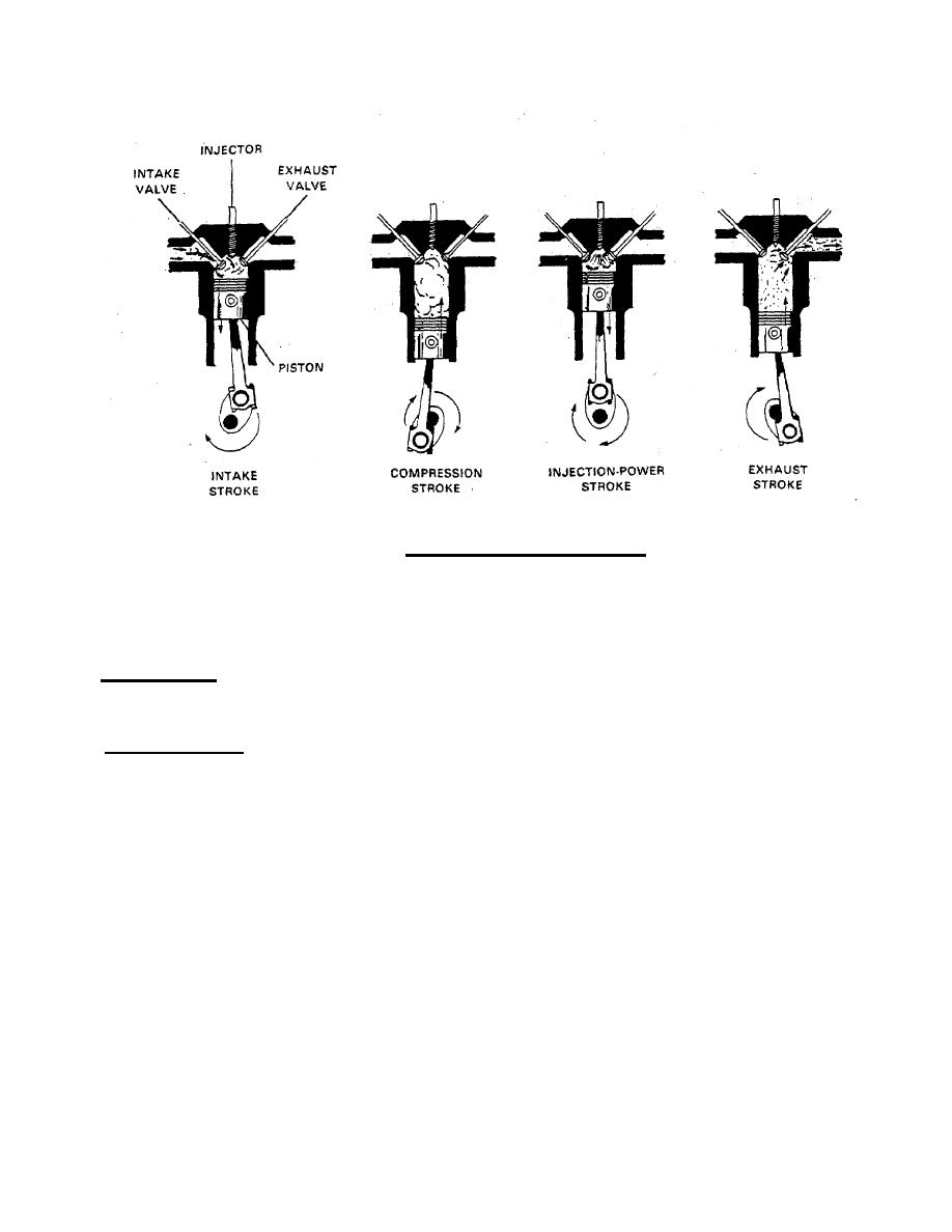
FIGURE 1-2. Four-Stroke Diesel Engine Cycles. |
|
||
| ||||||||||
|
|
 TM 55-1905-223-24-4
FIGURE 1-2. Four-Stroke Diesel Engine Cycles.
(4) Exhaust Stroke. During exhaust stroke, intake valve is closed, exhaust valve open, and piston on upstroke.
Upward travel of piston forces burned gases out of combustion chamber through open exhaust valve port and into the
exhaust manifold.
b. Cooling System. The radiator is filled with a 50% mixture of water and coolant, which is circulated through the
engine by a centrifugal-type water pump. Heat is removed from the coolant by the radiator. Control of the temperature
is accomplished by a thermostat.
c. Lubrication System. Tthe 4BT3.9GC engine is pressure lubricated by a gear-type oil pump at the-rear of the
engine. The pump is mounted to the block, directly below the crankshaft, and is driven from the rear crankshaft gear.
The pump draws the oil from the pan and forces it through the lubrication system in the following sequence:
(1) Oil is drawn from the pan to the oil cooler. A pressure regulating valve controls the oil pressure and passes
excess oil back to the pan.
(2) The oil then passes through the oil cooler to the filter. A filter bypass valve ensures a supply of oil in the event
the filter becomes plugged.
(3) From the filter, oil flows to the main oil passage in the engine block. This provides lubrication to all moving
parts. At the same time oil is routed to the turbocharger through external lines.
1-6
|
|
Privacy Statement - Press Release - Copyright Information. - Contact Us |
