 |
|||
|
|
|||
|
Page Title:
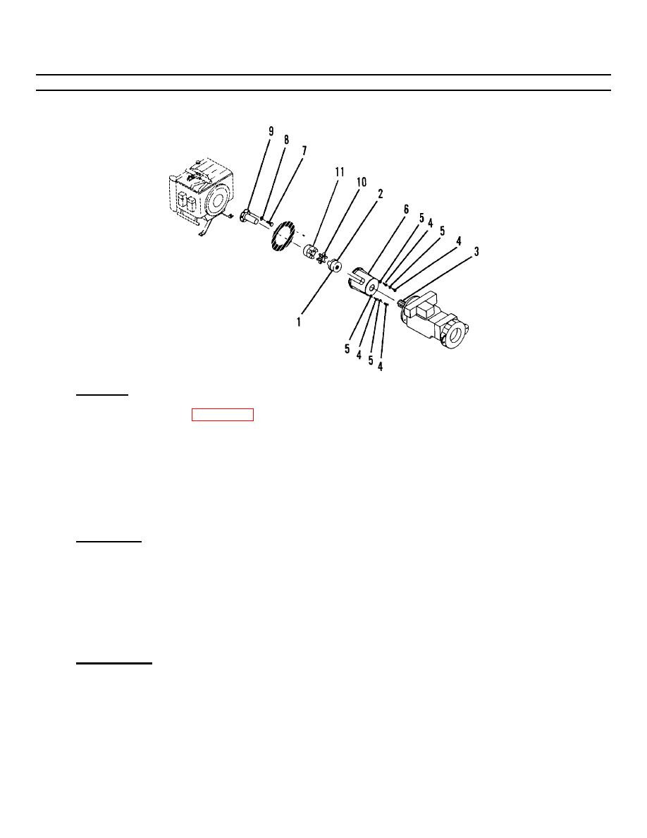
Figure 4-46. Stub Shaft and Coupling (Sheet 2 of 2). |
|
||
| ||||||||||
|
|
 TM55-1730-228-13&P
4-35. STUB SHAFT AND COUPLING - REPLACE (Continued)
4-35
Figure 4-46. Stub Shaft and Coupling (Sheet 2 of 2).
a. REMOVAL:
(1) Loosen setscrew (1, Figure 4-46) in coupling (2) on the transmission side.
(2) Slide coupling (2) off the transmission input shaft (3).
(3) Remove capscrews (4) and washers (5) securing guard (6) and remove guard (6).
(4) Remove capscrews (7) and washers (8) securing stub shaft (9) and remove stub shaft (9).
(5) Separate coupling (10) and coupling (11).
b. INSPECTION:
(1) Examine stub shaft (9) for missing teeth, nicks, deep scratches, evidence of misalignment or other
damage. Replace if necessary.
(2) Examine the flexible coupling (10) for damage to metal parts. Check the urethane spider. If it is
damaged, it must be replaced. If the spider is damaged, examine the metal areas where it makes contact.
If the spider is so badly damaged that the damage extends to the metal areas, the entire coupling must be
replaced.
c. INSTALLATION:
(1) Install stub shaft (9) and secure with capscrews (7) and washers (8).
GO ON TO NEXT PAGE
4-124
|
|
Privacy Statement - Press Release - Copyright Information. - Contact Us |
