 |
|||
|
|
|||
|
Page Title:
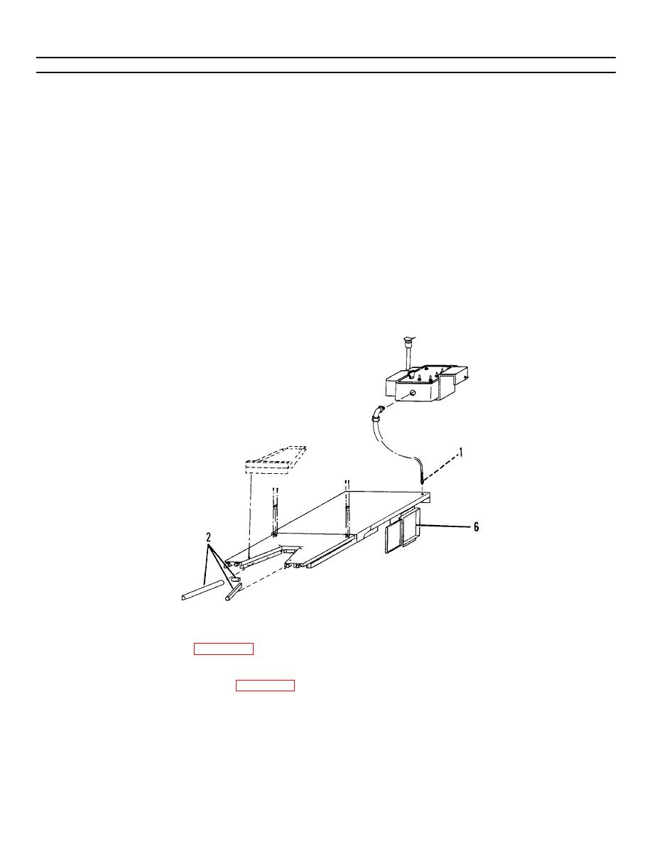
Figure 4-33.1. Platform Cables. |
|
||
| ||||||||||
|
|
 TM 55-1730-228-13&P
4-27. PLATFORM - REPLACE (Continued)
4-27
(2) Place four camfollowers (18) in position on scissors (19) and install four washers (17), and four nuts (16).
(3) Remove hoist and slings.
(4) Install junction box (6) and secure with four capscrews (5), washers (4), washers (3), lockwashers (2) and nuts (1).
(5) Install platform control box cable (13) through platform (7).
(6) Install nut securing strain relief fitting (12) to platform (7).
(7) Position safety bumpers and cables (11) on platform (7) and secure with screws (10).
(8) Route two limit switch cables on platform (7) to junction box (6).
(9) Secure bumper and limit switch cables to platform (7) with tie straps.
(10) Install bumper (9) on platform (7) using screw (8).
(11) Reinstall platform light socket.
Figure 4-33.1. Platform Cables.
(12) Install bumper (1 and 2, Figure 4-33.1) and limit switch cables through fittings in junction box (6) using tags for
identification.
(13) Install the strain relief covers (1, Figure 4-33.2) for the control box, bumper, platform light and limit switc h cables
on the fittings of junction box (2).
GO ON TO NEXT PAGE
4-93
|
|
Privacy Statement - Press Release - Copyright Information. - Contact Us |
