 |
|||
|
|
|||
|
Page Title:
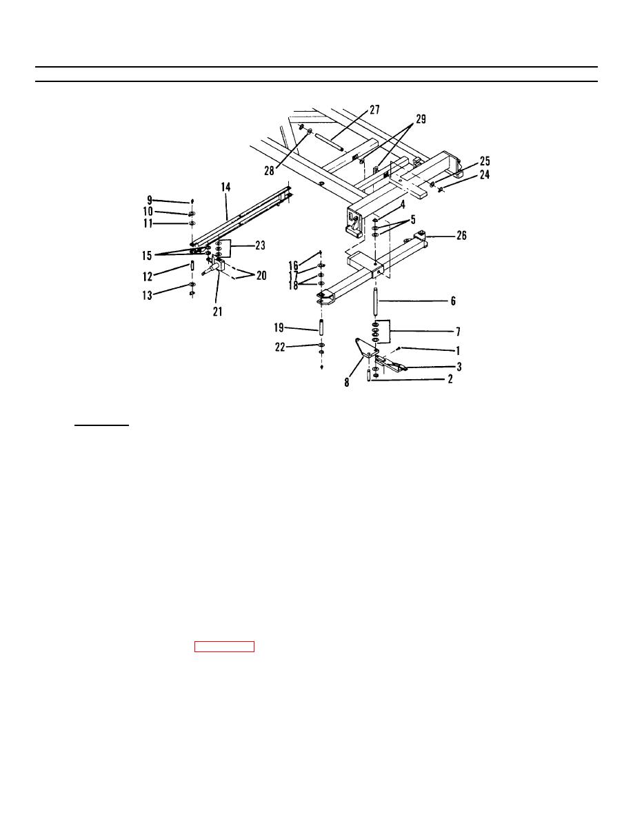
Figure 4-26. Steering Assembly (Sheet 2 of 3). |
|
||
| ||||||||||
|
|
 TM 55-1730-228-13&P
4-23. STEERING ASSEMBLY - REPLACE (Continued)
4-23
Figure 4-26. Steering Assembly (Sheet 2 of 3).
a. REMOVAL:
WARNING
Do not depend on a floor jack to support the SPEMS. Use jack stands for this purpose.
NOTE
Both sides of steering assembly are removed the same way, right side is illustrated.
NOTE
During removal, tag and note the locations and quantities of spacers for ease of reassembly.
(1) Place the floor jack under the front frame member and raise SPEMS.
(2) Support the frame with jack stands. Position the stands under the support to the rear of the steering
assembly. Remove the floor jack.
(3) Remove set screw (1, Figure 4-26) and rear drag link pin (2).
(4) Remove towing tongue link (3).
(5) Remove retaining ring (4) and spacer set (5).
(6) Remove front tie rod link pin (6) and spacer set (7).
(7) Remove tie rod link (8).
GO ON TO NEXT PAGE
4-78
|
|
Privacy Statement - Press Release - Copyright Information. - Contact Us |
