 |
|||
|
|
|||
|
Page Title:
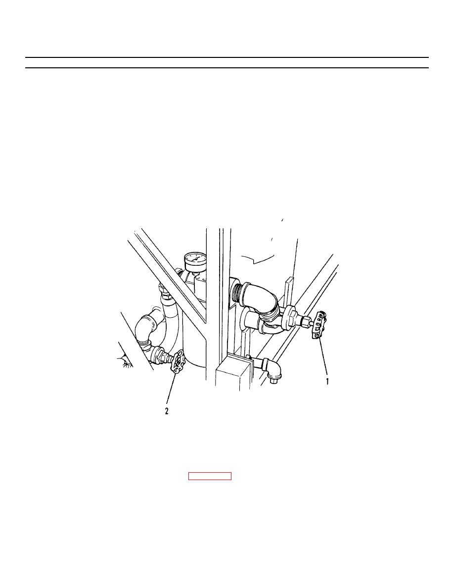
Figure 4-21.1. Hydraulic System Gate Valves. |
|
||
| ||||||||||
|
|
 TM 55-1730-228-13&P
4-18. TRANSMISSION - REPLACE (Continued)
4-18
(4) Maneuver the transmission (4) until you can insert the engine output shaft (or stub shaft) into the flexible
coupling (16).
(5) Install transmission support (14) and capscrews (11), washers (13) and lockwashers (12).
Tighten
capscrews securely.
(6) Install two socket head capscrews and washers (9) that hold transmission (4) to adapter (10). Tighten
socket head capscrews securely.
(7) Place large u-bolt (6) in position and install nuts (5).
(8) Remove plugs and install transmission hydraulic hoses. Use tags for identification.
(9) Install cables to transmission control solenoids (7 and 8) using the tags for identification and secure with
screws.
Figure 4-21.1. Hydraulic System Gate Valves.
(10) Carefully position the manifold block (3) on the transmission (4).
(11) Install capscrews (1) and washers (2).
(12) Open suction gate valves (1 and 2, Figure 4-21.1) fully counterclockwise.
(13) Start and run SPEMS. Check for oil leaks.
(14) Check hydraulic reservoir level and refill if necessary.
END OF TASK
4-65
|
|
Privacy Statement - Press Release - Copyright Information. - Contact Us |
