 |
|||
|
|
|||
|
Page Title:
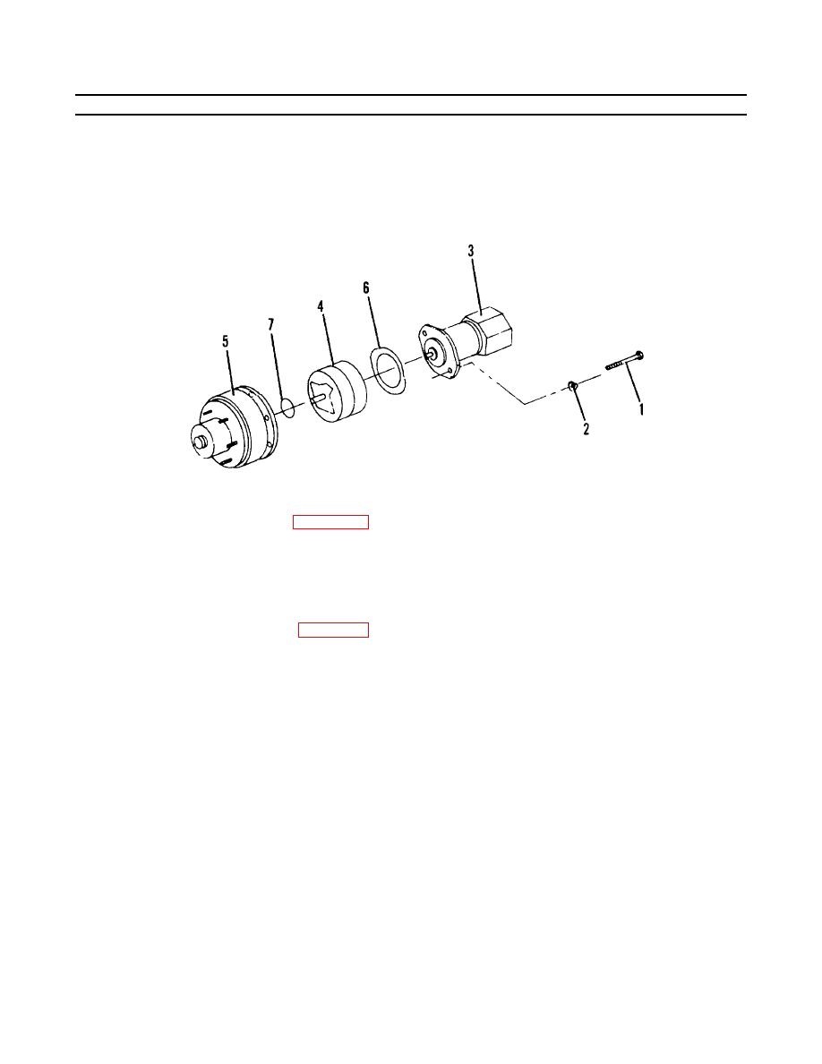
Figure 4-14.1. Drive Hub Replacement . |
|
||
| ||||||||||
|
|
 TM55-1730-228-13&P
4-12.
HYDRAULIC MOTOR, BRAKE AND DRIVE HUB ASSEMBLY- REPAIR (Continued)
4-12
NOTE
Install coupling so that counterbore of coupling faces out.
(aa) Slide coupling (1) on input shaft (2).
Figure 4-14 . 1 .
Drive Hub Replacement .
(ab) Place a new gasket (6, Figure 4-14.1) on the face of the drive motor assembly (3).
(ac) Place a new preformed packing (7) on the face of the brake assembly (4).
(ad) Align the holes of the drive hub assembly (5), brake assembly (4) and drive motor assembly (3)
and install two capscrews (1) and washers (2). Tighten capscrews securely.
(ae) Service drive hub. See para 3-27.
(af) Perform operational check for proper function.
END OF TASK
4-46
|
|
Privacy Statement - Press Release - Copyright Information. - Contact Us |
