 |
|||
|
|
|||
|
Page Title:
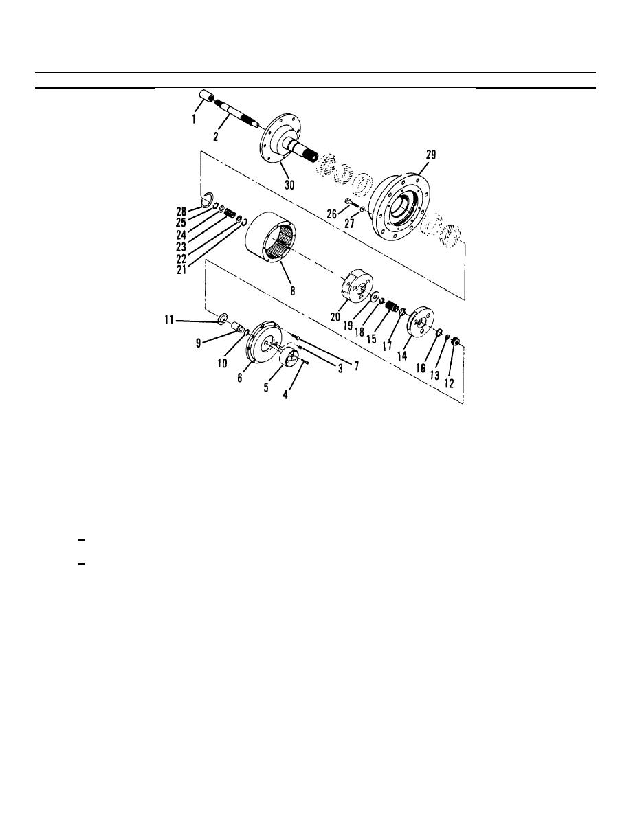
Figure 4-14. Drive Hub Assembly (Sheet 3 of 3). |
|
||
| ||||||||||
|
|
 TM55-1730-228-13&P
4-12. HYDRAULIC MOTOR, BRAKE AND DRIVE HUB ASSEMBLY- REPAIR (Continued)
4-12
Figure 4-14. Drive Hub Assembly (Sheet 3 of 3).
NOTE
Bearing should have .000-.012 inches (.00-0.3 mm) of end play when proper snap ring is installed.
(g) Select the thickest retaining ring (28) that will fit in the ring groove of spindle above the bearing cone.
(h) Assemble input shaft (2).
1
Install retaining ring (25) on input shaft.
2
Assemble washer (24), spring (23) and washer (22) on shaft. Secure with retaining ring (21).
(i) Install the splined end of input shaft assembly (2) down through spindle (30).
(j) Install secondary carrier assembly (20) over splined end of spindle (30).
NOTE
Install carrier with the pinion shaft retaining rings down.
(k) Thoroughly clean the surface and apply a continuous bead of silicone sealer to he face of hub (29) that
t
mates with the ring gear (8). Center the bead on the sealing surface staying inside of bolt holes.
GO ON TO NEXT PAGE
4-44
|
|
Privacy Statement - Press Release - Copyright Information. - Contact Us |
