 |
|||
|
|
|||
|
Page Title:
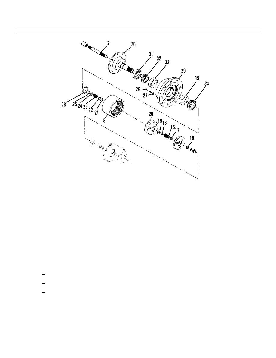
Figure 4-14. Drive Hub Assembly (Sheet 2 of 3). |
|
||
| ||||||||||
|
|
 TM55-1730-228-13&P
4-12. HYDRAULIC MOTOR, BRAKE AND DRIVE HUB ASSEMBLY- REPAIR (Continued)
4-12
Figure 4-14. Drive Hub Assembly (Sheet 2 of 3).
NOTE
Large sun gear (15) will come out with carrier.
(k) Expand retaining ring (16) and remove large sun gear (15).
(l) Remove retaining ring (16).
(m) Remove retaining ring (17) from large sun gear (15).
(n) Remove retaining ring (18) and thrust washer (19) from input shaft (2).
(o) Remove secondary carrier assembly (20).
(p) Remove input shaft assembly (2).
(q) Disassemble input shaft assembly.
1 Remove retaining ring (21).
2
Remove washer (22) and spring (23) and washer (24).
3
Remove retaining ring (25).
(r) Remove capscrews (26) and washers (27) securing ring gear (8). Tap ring gear with a soft faced mallet
and remove gear.
(s) Remove retaining ring (28).
GO ON TO NEXT PAGE
4-42
|
|
Privacy Statement - Press Release - Copyright Information. - Contact Us |
