 |
|||
|
|
|||
|
Page Title:
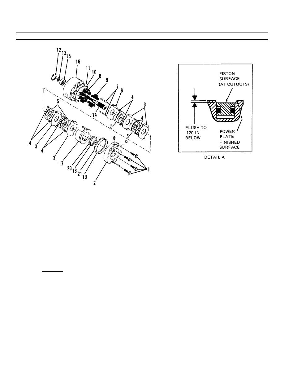
Figure 4-12. Hydraulic Brake Assembly (Sheet 2 of 2). |
|
||
| ||||||||||
|
|
 TM55-1730-228-13&P
4-12. HYDRAULIC MOTOR, BRAE AND DRIVE HUB ASSEMBLY- REPAIR (Continued)
4-12
Figure 4-12. Hydraulic Brake Assembly (Sheet 2 of 2).
(j) Remove shaft (14) from bearing (15) by lightly tapping shaft with soft faced mallet.
(k) Remove retaining ring (12) and press bearing (15) from housing (16). Be sure piston is directed away
from personnel during removal. Failure to do so may result in personnel injury.
(l) Remove piston (17) from power plate (2) by introducing low pressure air (15 psi max.) into the hydraulic
inlet.
(m) Remove preformed packing (18) and back-up ring (20) from inside piston and discard.
(n) Remove preformed packing (19) and back-up ring (21) from piston and discard.
(2) Inspection:
(a) Clean all parts with cleaning solvent and dry with a lint-free cloth.
(b) Inspect moving parts for evidence of wear, burrs, nicks, chips, scoring and other damage.
(c) Replace damaged parts with new parts.
GO ON TO NEXT PAGE
4-38
|
|
Privacy Statement - Press Release - Copyright Information. - Contact Us |
