 |
|||
|
|
|||
|
Page Title:
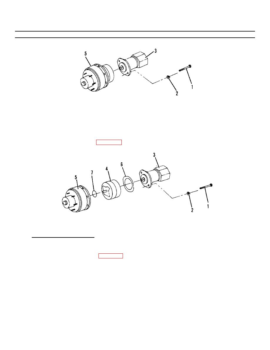
Figure 4-10.3. Hydraulic Motor Assembly. |
|
||
| ||||||||||
|
|
 TM55-1730-228-13&P
4-12. HYDRAULIC MOTOR, BRAKE AND DRIVE HIB ASSEMBLY- REPAIR (Continued)
4-12
Figure 4-10.3. Hydraulic Motor Assembly.
NOTE
You may have to turn motor shaft to mesh splining.
(q) Mate motor assembly (3, Figure 4-10.3) to brake/drive hub (5) assembly. Secure motor assembly with
two capscrews (1) and washers (2).
Figure 4-11. Hydraulic Brake Replacement.
b. HYDRAULIC BRAKE - REPAIR.
(1) Disassembly:
(a) Remove two capscrews (1, Figure 4-11) and washers (2) securing drive motor assembly (3) to brake
assembly (4) and drive hub (5).
(b) Remove motor assembly (3), remove gasket (6) and discard.
(c) Remove brake assembly (4) from drive hub (5).
(d) Remove preformed packing (7) and discard.
(e) Scribe the brake housing for ease of reassembly.
GO ON TO NEXT PAGE
4-36
|
|
Privacy Statement - Press Release - Copyright Information. - Contact Us |
