 |
|||
|
|
|||
|
Page Title:
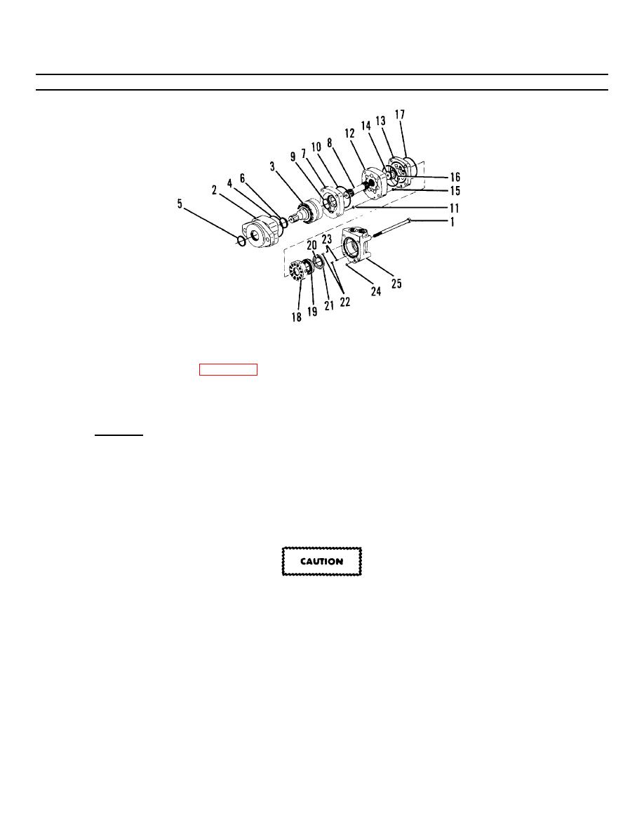
Figure 4-10.1. Hydraulic Motor Assembly. |
|
||
| ||||||||||
|
|
 TM55-1730-228-13&P
4-12. HYDRAULIC MOTOR, BRAKE AND DRIVE HUB ASSEMBLY- REPAIR (Continued)
4-12
Figure 4-10.1. Hydraulic Motor Assembly.
(n) Remove valve (18, Figure 4-10.1) balance ring (19), seals (20 and 21), two pins (22) and two springs
(23). Discard seals.
(o) Remove preformed packing (24) from valve housing (25).
(2) Inspection:
(a) Clean all parts with cleaning solvent and dry with a lint-free cloth.
(b) Inspect moving parts for evidence of wear, burrs, nicks, chips, scoring and other damage.
(c) Replace damaged parts with new parts.
(3) Assembly:
Internal components of hydraulic assemblies are machined to very close tolerances and can be damaged by rough
handling or forced assembly. If a component doesn't seem to fit properly, don't force it, it may be slightly out of
alignment. Remove the component and try again until it slides easily into position.
NOTE
Lubricate all parts with clean hydraulic oil before assembly.
(a) Install two springs (23) two pins (22), and new preformed packing (24) in valve housing (25).
(b) Place preformed packing (17) into position on the face of the valve housing.
GO ON TO NEXT PAGE
4-34
|
|
Privacy Statement - Press Release - Copyright Information. - Contact Us |
