 |
|||
|
|
|||
|
Page Title:
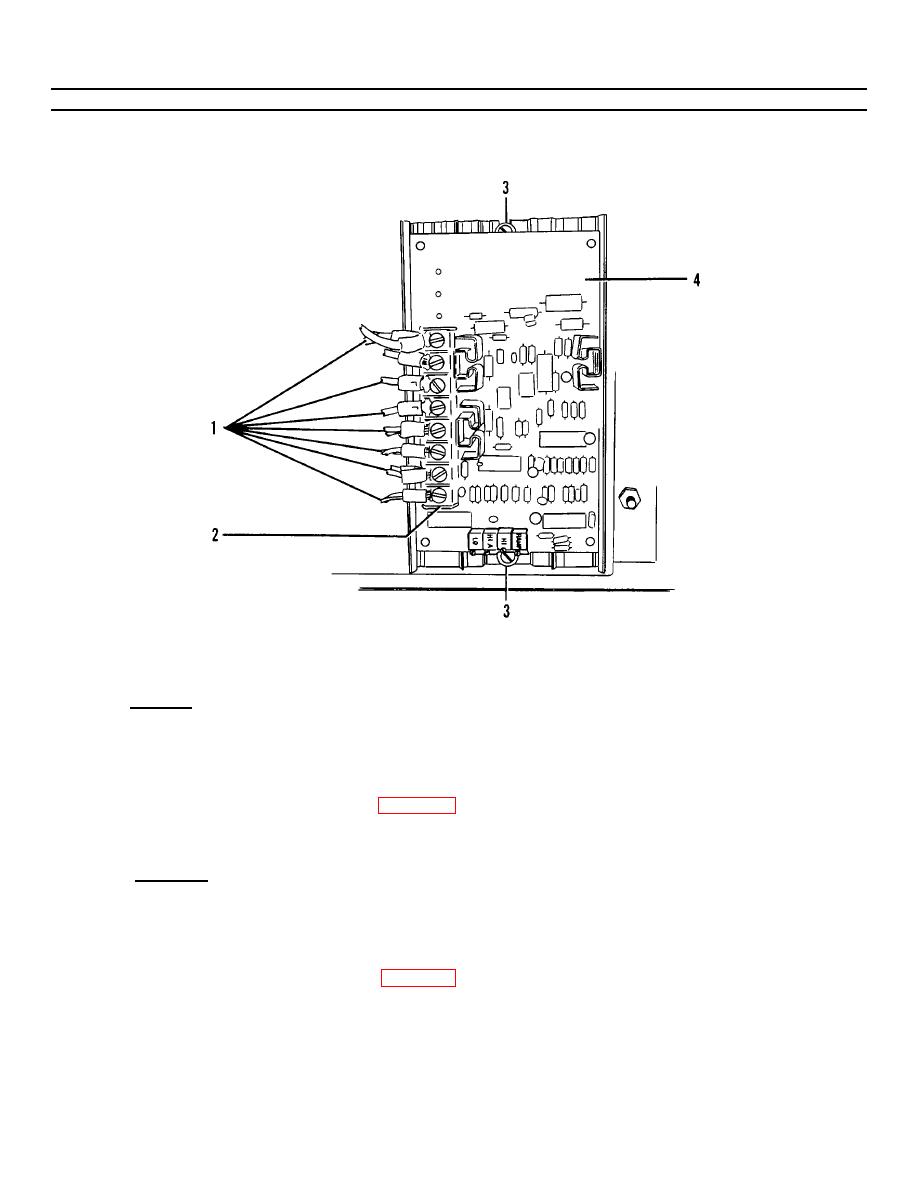
Figure 4-5. Printed Circuit Board Replacement. |
|
||
| ||||||||||
|
|
 TM55-1730-228-13&P
4-11. JUNCTION BOXES - REPAIR (Continued)
4-11
(4) Refer to the electrical troubleshooting information for general procedures on circuit testing.
Figure 4-5. Printed Circuit Board Replacement.
b. REPLACEMENT OF PRINTED CIRCUIT BOARD:
(1) Removal:
NOTE
Tag all wires for ease in reassembly.
(a) Tag and remove eleven wires ( 1, Figure 4-5) from printed circuit board terminal strip (2).
(b) Remove two screws (3) from printed circuit board (4), remove board and discard.
(2) Installation:
(a) Position new printed circuit board (4) in junction box and install two screws (3).
(b) Connect previously tagged wires (1) to printed circuit board terminal strip (2).
(c) Adjust printed circuit board. See para 4-10.
GO ON TO NEXT PAGE
4-29
|
|
Privacy Statement - Press Release - Copyright Information. - Contact Us |
