 |
|||
|
|
|||
|
Page Title:
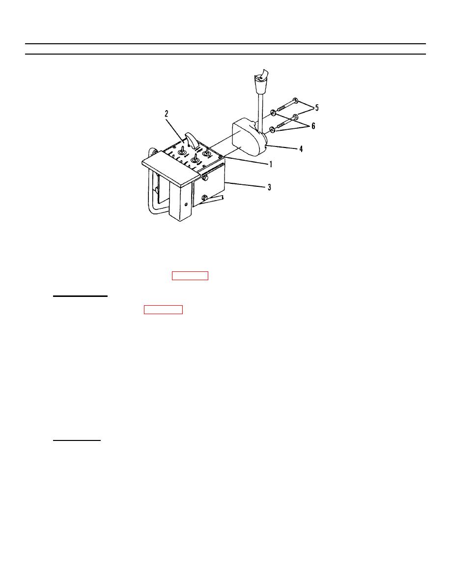
Figure 4-2. Control Box Repair (Sheet 2 of 2) . |
|
||
| ||||||||||
|
|
 TM 55-1730-228-13&P
4-8. CONTROL BOXES - REPAIR (Continued)
4-8
Figure 4-2.
Control Box Repair (Sheet 2 of 2) .
NOTE
Refer to para 3-22 for toggle switch replacement.
a. DISASSEMBLY:
(1) Remove eight screws (1, Figure 4-2) securing cover and gasket (2) to control box (3).
(2) Lift cover and gasket (2) and allow to hang.
(3) Identify the wires coming from the control lever (4) and tag for ease of reassembly.
(4) Disconnect the wires coming from the control lever (4).
(5) Identify the wires coming from the micro switch and tag for ease of reassembly.
(6) Disconnect the wires coming from the micro switch at the barrier strip.
(7) Remove two capscrews (5) with lockwashers (6) securing control lever assembly (4) to control box (3).
Remove control lever assembly (4).
b. INSPECTION.
(1) Clean all parts with cleaning solvent and dry with a lint-free cloth.
(2) Inspect moving parts for evidence of wear, burrs, nicks, chips, scoring and other damage.
(3) Replace damaged parts with new parts.
GO ON TO NEXT PAGE
4-22
|
|
Privacy Statement - Press Release - Copyright Information. - Contact Us |
