 |
|||
|
|
|||
|
Page Title:
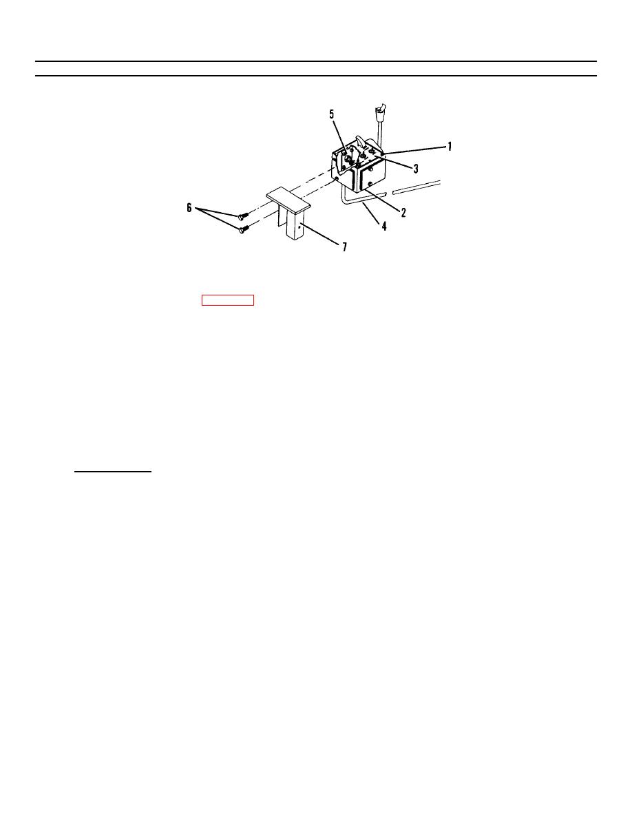
Figure 4-1. Control Box Replacement (Sheet 2 of 2) . |
|
||
| ||||||||||
|
|
 TM 55-1730-228-13&P
4-7. CONTROL BOXES - REPLACE (Continued)
4-7
Figure 4-1 .
Control Box Replacement (Sheet 2 of 2) .
(1) Remove eight screws (1, Figure 4-1) from control box (2).
(2) Lift cover and gasket (3) and allow to hang.
(3) Tag each wire in cable (4) for ease of reassembly.
(4) Disconnect each wire in cable (4).
(5) Remove elbow (5) with cable (4) from control box (2).
(6) Carefully pull cable (4) out of control box (2).
(7) Remove two capscrews (6) securing bracket (7) to control box (2).
b. INSTALLATION:
(1) Attach bracket (7) to control box (2) with two capscrews (6).
(2) Carefully insert cable (4) with elbow (5) through hole in control box (2).
(3) Screw control box (2) onto elbow (5).
(4) Connect each wire in cable (4) using the tags for terminal identification.
(5) Position cover and gasket (3) on control box (2) and secure with eight screws (1).
(6) Perform operational check for proper function.
END OF TASK
4-20
|
|
Privacy Statement - Press Release - Copyright Information. - Contact Us |
