 |
|||
|
|
|||
|
Page Title:
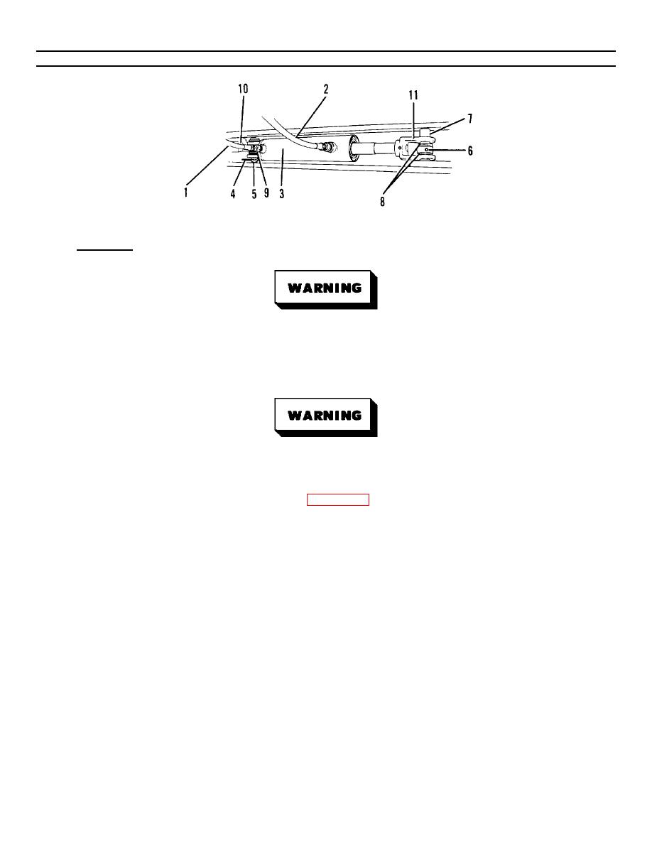
Figure 3-39. Steering Cylinder (Sheet 2 of 2). |
|
||
| ||||||||||
|
|
 TM55-1730-228-13&P
3-37. STEERING CYLINDER - REPLACE (Continued)
3-37
Figure 3-39. Steering Cylinder (Sheet 2 of 2).
a. REMOVAL:
Some hoses may contain small amounts of trapped hydraulic pressure. Wear protective clothing including
a face shield, head gear and gloves. Fine streams of hydraulic fluid under pressure cannot be readily
seen but can easily penetrate the skin causing severe personal injury. Use extreme caution and be alert
whenever breaking into a hydraulic system.
Hydraulic fluid may be extremely hot. Allow the SPEMS to stand fifteen minutes before breaking into
hydraulic system.
(1) Tag the cylinder hydraulic hoses (1 and 2, Figure 3-39) for easy identification durin installation. Place a
g
suitable container under the cylinder ports to catch fluid.
(2) Using two wrenches, disconnect the hydraulic hoses (1 and 2) to the cylinder (3). Plug the cylinder ports
and hoses to prevent foreign matter from entering the system.
NOTE
Note the location of spacer sets and tag each set during removal for easy identification during installation.
(3) Remove the pin clip (4) from the cylinder eye pin (5).
(4) Place a prybar under the cylinder tube between the tie rod member andcylinder for support.
(5) Remove the cylinder eye pin (5) from the top.
GO ON TO NEXT PAGE
3-96
|
|
Privacy Statement - Press Release - Copyright Information. - Contact Us |
