 |
|||
|
|
|||
|
Page Title:
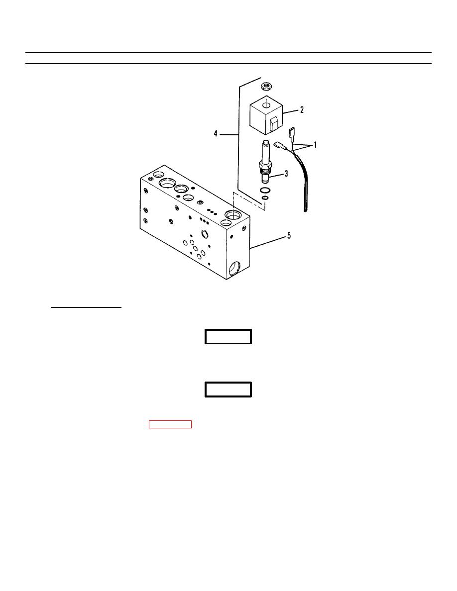
Figure 3-32. Solenoid Valve/Cartridge Assembly (Sheet 2 of 2). |
|
||
| ||||||||||
|
|
 TM 55-1730-228-13&P
3-31. SOLENOID VALVES/ CARTIDGES - REPLACE (Continued)
3-31
Figure 3-32. Solenoid Valve/Cartridge Assembly (Sheet 2 of 2).
a. SOLENOID VALVES:
(1) Removal:
WARNING
Some hoses may contain small amounts of trapped hydraulic pressure. Wear protective clothing including a face shield,
head gear and gloves. Fine streams of hydraulic fluid under pressure cannot be readily seen but can easily penetrate the
skin causing severe personal injury. Use extreme caution and be alert whenever breaking into a hydraulic system.
WARNING
Hydraulic fluid may be extremely hot. Allow the SPEMS to stand fifteen minutes before breaking into hydraulic system.
(a) Tag and remove the leads (1, Figure 3-32) from the solenoid (2).
NOTE
On lift cylinder solenoids a connector is used. Remove the screw securing the connector to the solenoid and pull straight
off.
(b) Unscrew the solenoid cartridge (3) using a wrench on the large hex fitting closest to the valve body. Remove the
solenoid valve/cartridge assembly (4).
(c) Plug the valve body (5) to keep foreign matter from entering the system.
GO ON TO NEXT PAGE
3-78
|
|
Privacy Statement - Press Release - Copyright Information. - Contact Us |
