 |
|||
|
|
|||
|
Page Title:
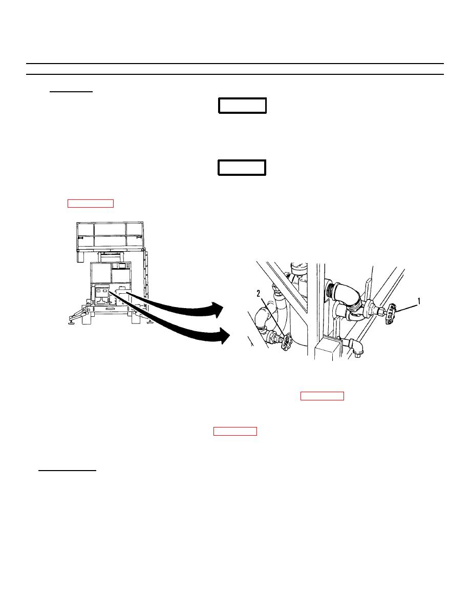
Figure 3-31.1. Gate Valves. |
|
||
| ||||||||||
|
|
 TM 55-1730-228-13&P
3-30. SUCTION AND INLIT FILTERS - REPLACE (Continued)
3-30
a. REMOVAL:
WARNING
Some hoses may contain small amounts of trapped hydraulic pressure. Wear protective clothing including a face
shield, head gear and gloves. Fine streams of hydraulic fluid under pressure cannot be readily seen but can easily
penetrate the skin causing severe personal injury. Use extreme caution and be alert whenever breaking into a
hydraulic system.
WARNING
Hydraulic fluid may be extremely hot. Allow the SPEMS to stand fifteen minutes before breaking into hydraulic
system. Figure 3-31.1. Gate Valves.
Figure 3-31.1. Gate Valves.
(1) Close (turn fully clockwise) the suction and return gate valves (1 and 2, Figure 3-31.1).
(2) Place a drip pan under the filter.
(3) Using strap wrench, unscrew filter element (1, Figure 3-31) and discard.
(4) Remove gasket (2) from filter base (3) and discard.
b. INSTALLATION:
(1) Lubricate gasket (2) with clean hydraulic fluid and install in filter base (3).
GO ON TO NEXT PAGE
3-75
|
|
Privacy Statement - Press Release - Copyright Information. - Contact Us |
