 |
|||
|
|
|||
|
Page Title:
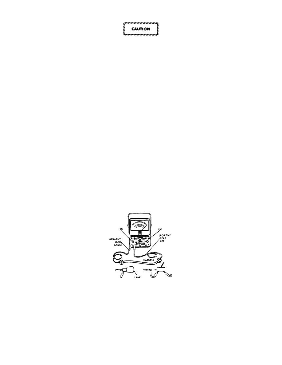
Figure 3-15. Continuity Check With Multimeter. |
|
||
| ||||||||||
|
|
 TM55-1730-228-13&P
Failure to do the following step can damage the multimeter.
b. Disconnect the circuit being checked. To be safe, disconnect the battery ground cable.
c. Connect the meter probes to both terminals of the circuit being checked.
d. Observe needle movement.
(1) If the needle swings to the far right over the 0 on the top scale, the circuit has continuity.
(2) If the needle doesn't move, the circuit is open (broken).
(3) If the needle jumps or flickers, there is a loose connection in the circuit being checked.
Quick Reference
CONTINUITY CHECK
(1) SET SCALE SELECTOR ON +DC.
(2) SET RANGE SELECTOR SWITCH ON R x 1.
(3) BE SURE THERE IS NO BATTERY VOLTAGE CONNECTED TO CIRCUIT TO BE CHECKED.
(4) ATTACH NEGATIVE LEAD (BLACK) TO ONE END OF CIRCUIT.
(5) TOUCH POSITIVE LEAD (RED) TO OTHER END OF CIRCUIT. NEEDLE SHOULD MOVE TO RIGHT
HAND END OF SCALE.
(6) IF NEEDLE DOESN'T MOVE, CIRCUIT IS OPEN.
(7) IF NEEDLE FLICKERS, OR JUMPS BACK AND FORTH, CHECK FOR LOOSE CONNECTIONS IN THE
CIRCUIT.
Figure 3-15. Continuity Check With Multimeter.
GO ON TO NEXT PAGE
3-15
|
|
Privacy Statement - Press Release - Copyright Information. - Contact Us |
